Helium Airship Projects
Aeromechanics Ltd was instrumental in the nine major
Airship projects illustrated in this gallery, seven of which successfully took to the skies.
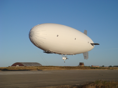
The SAIC SKYBUS 80K unmanned airship takes off from Limestone, Maine USA on one of many flight tests in pre-programmed mode under an FAA Special Airworthiness Experimental Certificate.
The SKYBUS 80K met or exceeded all of its design objectives including the principal criteria to carry a 500lb payload to 10,000ft for 24hrs without refuelling.
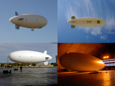
A Quad of pictures from envelope pressure test to pre-programmed flight.
Responsibilities once the design was completed included lead certification engineer, oversight of the Airship integration & ground tests and for the majority of the flight test program acting as Flight Test Director. Analysed hundreds of hours of flight test telemetry and video footage to validate performance characteristics.
Redesigned and structurally analysed the modified gondola engine frame for up-rated performance at altitude.
Designed, optimised and analysed the fins & control surfaces for critical gust cases to meet manned airship requirements.
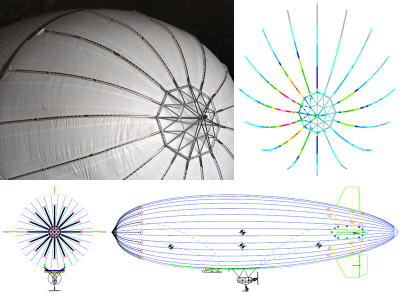
Undertook the preliminary and final design of the Nose Cone and Nose Battens integrated on the flexible membrane structure (envelope) employing Finite Element techniques.
Performed detail sizing & performance analysis based on modified envelope shape generators to produce a scalable family of airships. Also specified the envelope material requirements to obtain significantly enhanced helium retention capabilities compared to industry accepted norms.
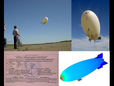
The SKYBUS programme was granted the US’s first certificate for an Experimental Unmanned airship.
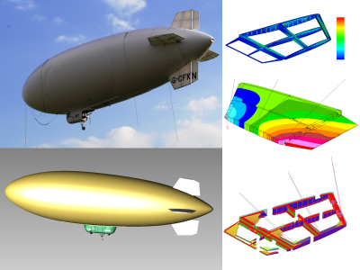
Design and structural certification analysis of the composite fins for the Lindstrand Technologies GA22+ unmanned airship.
Tasks also included the derivation of the composite design allowables based on the material test programme instigated and advisor for the manufacturing program.
Design and structural certification analysis of the composite gondola and an assessment of the undercarriage for the Lindstrand Technologies GA22+ unmanned airship.
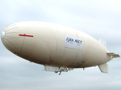
The JAXA (Japan Aerospace Exploration Agency) 12 tonne displacement experimental unmanned airship.
Aeromechanics Ltd was subcontracted to a US company to design, analyse and test the single castoring landing gear based on the design of an existing smaller system. In addition to this major design effort, technical support for the envelope’s nose stiffening assemblies and general airship technologies were provided.
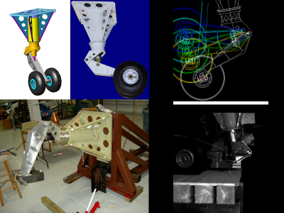
Clockwise from top left hand corner:
CAD model of complete assembly.
The finished article ready for delivery.
Computer simulation.
Physical drop test.
Static test rig for structural validation.
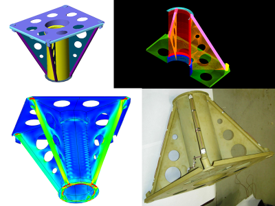
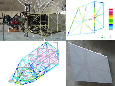
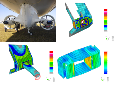
Clockwise from top left hand corner:
CAD model of support frame.
Finite Element mesh generated from CAD surface model.
The manufactured frame with strain gauges attached.
Colour contour plot from the Finite Element shell model showing an intensity field due to externally applied forces.
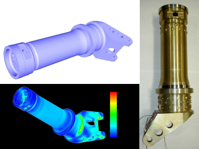
Top left: Solid model of main leg developed in CAD.
Bottom left: Colour contour plot from the Finite Element solid model.
Note, the FEA model often has to be de-featured after importing from CAD so that small details like fillet radii do not produce excessively large analysis files.
Right: The main leg machined assembly.
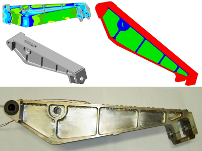
Pictures of the pivot arm from the CAD model (grey), Finite Element Analysis model (coloured) and the actual machined component (lower).
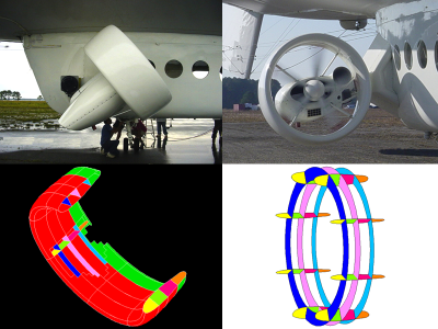
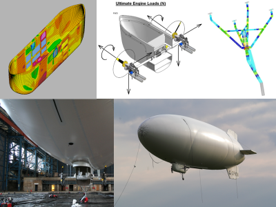
Aeromechanics Ltd was called upon to lead the US FAA certification effort for the Lycoming engine STC on the Santas-Dumont Skyship 600B for Airship Management Services Inc.
The modification entailed changing the power-plant type and location from gondola mounted Porsche engines to propulsor duct mounted Lycoming engines.
The propulsor duct structural Finite Element models are seen in the lower two pictures opposite where each separate colour
is a unique composite construction that could be laminate or sandwich construction or different materials, different fibre
orientation and different lamination thickness for example. This enables ease of manipulation for structural optimisation convergence.
Top left: Skyship 600B from the stern clearly showing the outriggers and propulsor duct. The remaining pictures show the Finite Element models for the outrigger.
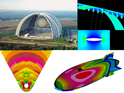
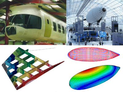
For a two year period (2000 to 2002), Aeromechanics Ltd formed part of the Envelope group to design and develop a 160 tonne payload capability airship for CargoLifter Development GmbH. At just over 1/4km (1/6 mile) long the CL160 airship was to be housed in the impressive purpose built hangar shown in the picture opposite [Top Left]
In the early stages of the project Aeromechanics constructed various Finite Element Models to assist the design engineers in their conceptual and preliminary designs whilst CargoLifter’s own FEA capability was emerging.
Aeromechanics also developed a test programme to characterise the critical tear length of airship envelopes using 10 to 40m long scale models.
Over and above the work described on this page, Aeromechanics also performed conceptual design and analyses of a spherical tethered balloon for precision crane operations to position payloads up to 100 tonnes.
One of the earliest major independent project undertakings that Aeromechanics Ltd performed was for the world renowned Per Lindstrand. In 1987 Per was in the midst of UK CAA BCAR Section Q certification for his two man GA42 helium airship.
Aeromechanics re-designed and optimised the composite fins and control surfaces having derived the aerodynamic lift distribution for the critical gust cases.
By early 1988 Aeromechanics had set up a UK CAA approved sister company, Hybrid Composites Ltd, to manufacture the large fins. Load testing under the scrutiny of the UK CAA was successful and Hybrid Composites built over eight ship sets.
Additional aerospace engineering tasks undertaken include an undercarriage lengthening modification and the re-design and strengthening of the aluminium nose cone mooring battens. A dynamic analysis was performed to assess the effect of envelope and mast frequencies due to an 80Kt gust case.
Aeromechanics also compiled the flight test schedules and performance reports for the Take off, landing, turning, climb and descent performance.
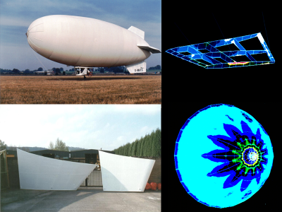
Some of the Airship projects Aeromechanics Ltd engaged in only reached a paper design level whilst others were part way through construction when halted. Nevertheless, leaving aside business and financial aspects, valuable engineering criteria can be learned from such exercises. Trying promotes progress.
Top left: ANR (Advanced Non Rigid) airship. Aeromechanics provided engineering trouble shooting on behalf of the Chief Executive and Chief designer. Introduced Workshop practises for the Composite manufacturing facility. Re-engineered, stressed and built the 0.5m diameter helium / air valves. Finite element analysis of the gondola cabin door and fin ruddervators.
Top Right: Design and build of a two place side by side interchangeable gondola for airships.
Bottom Right: Design and analysis of stratospheric airship platforms for communications.
Bottom left: Prototype design and analysis of composite fins for a large luxury airship cruiser.